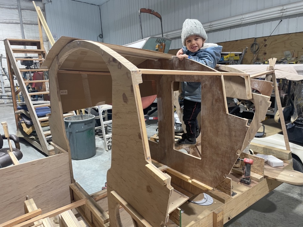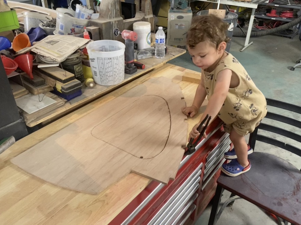
Slowly plugging away at more parts. My lunch hour consists of wolfing down a sandwich in about 10 minutes and then spending the rest of the time drawing or cutting out stuff. Later at home after supper I’ll often epoxy the parts together and work on the CAD drawings for the next day. Usually on the weekend I take my helper along to give my wife an afternoon to herself and he helps poke at the parts with some channel locks. Please excuse the pile-o-crap end of my coworker’s bench… I really need to put a wall up between it and my toolbox.
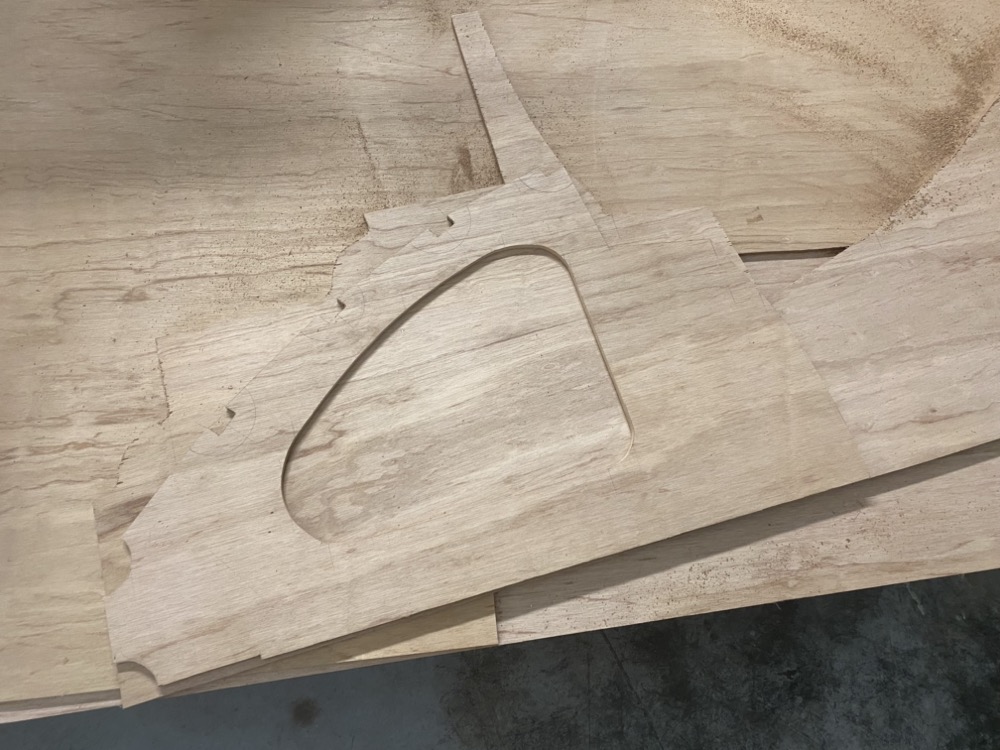
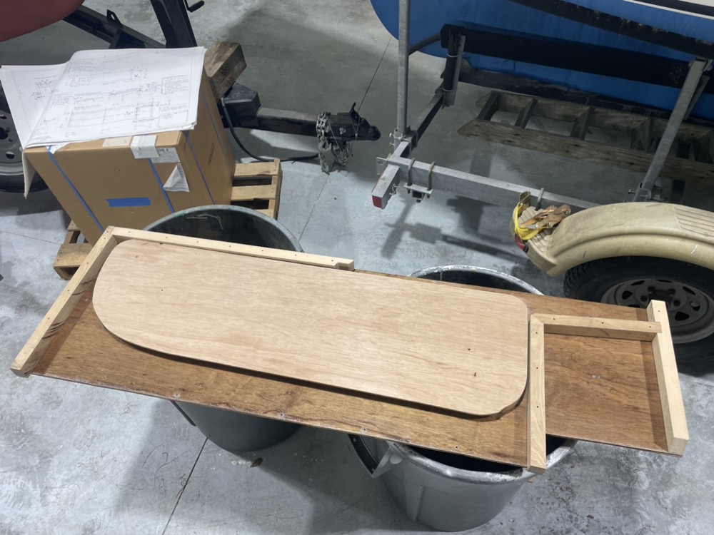
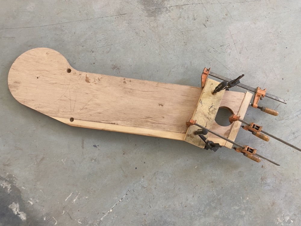
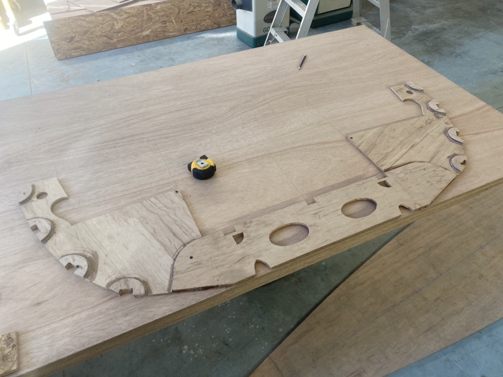
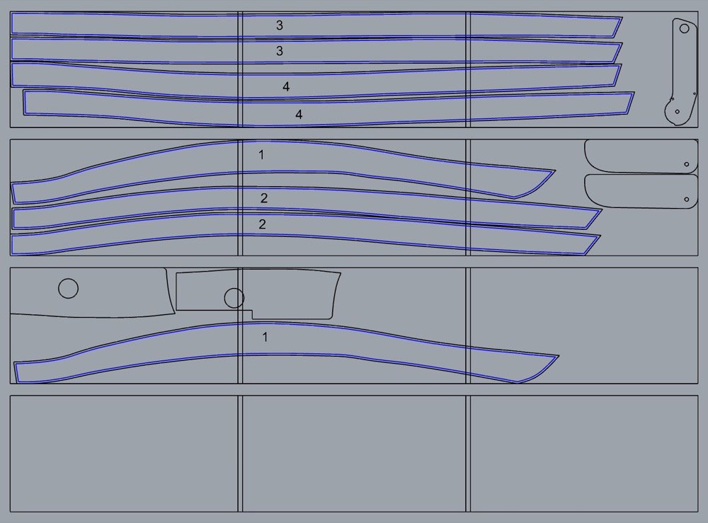
After cutting out the first half really accurately I lay it out on the last remaining bit of my sheet of ply. I’ll trace around it and cut it 1/4″ oversize, then screw the two pieces together and do the final trimming with a router and flush trim bit. I’ve been really pleased with how my CAD drawing and nesting the parts has worked out.
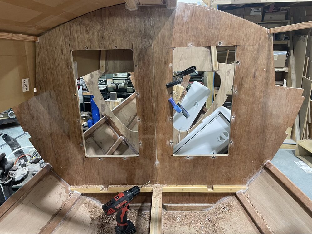
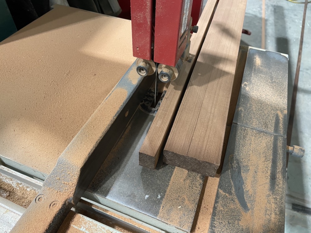
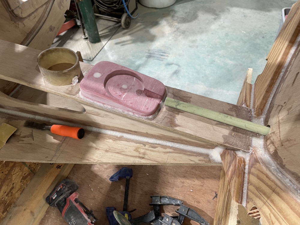
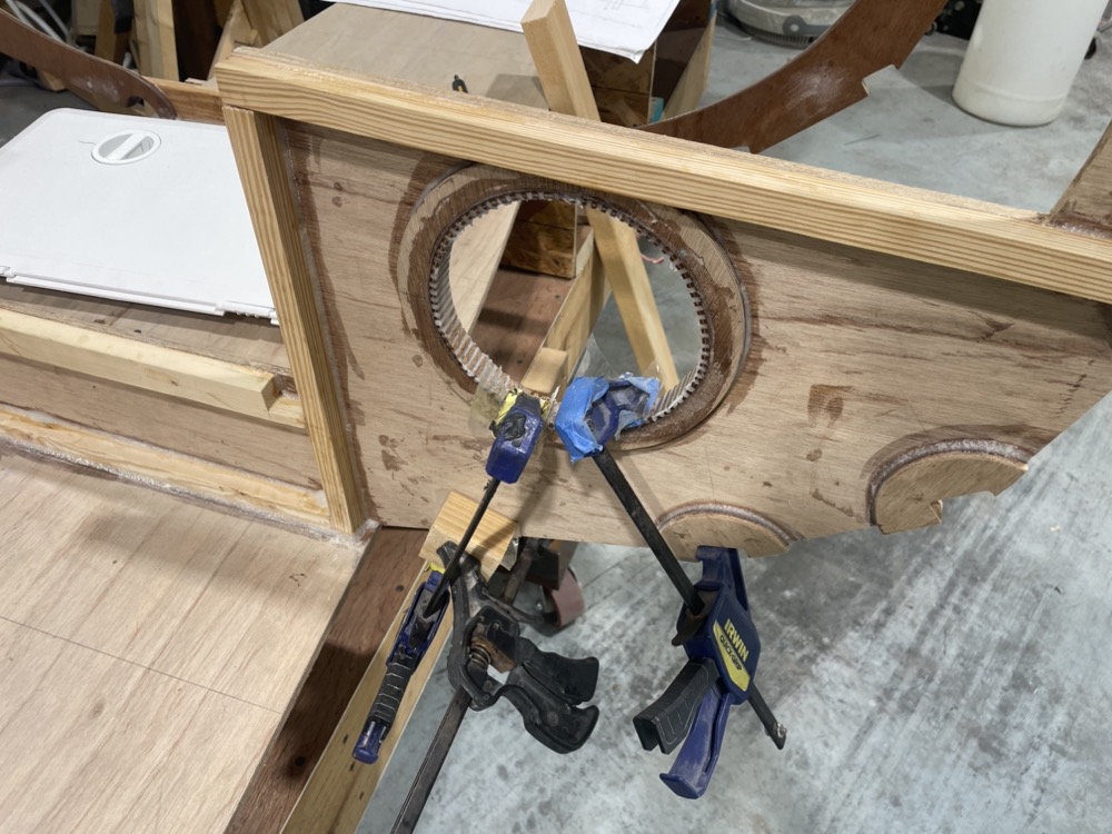
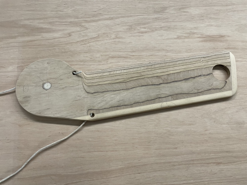
Two of the bulkheads aren’t symmetrical due to the offcenterboard, so I used the smaller side as a router template and drew in the missing part. Easy enough to bandsaw and plane that to size.
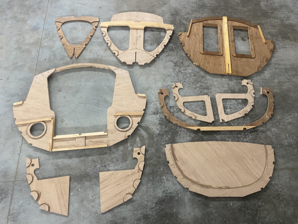
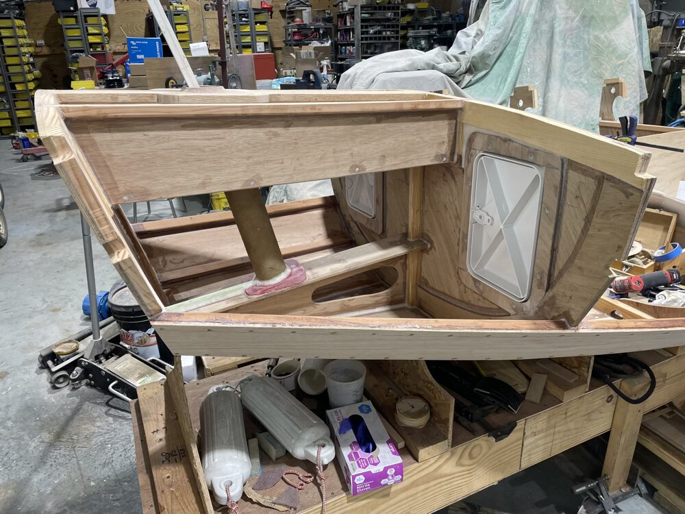
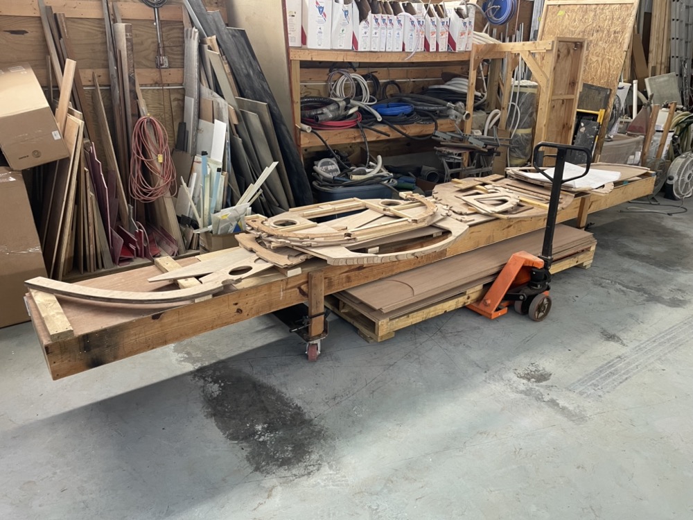
Here’s 8 of the 10 bulkheads in various stages of completion. On one hand it really bugs me that nothing is complete, but then again there’s always something I can use that last little bit of thickened epoxy on. I guess everything will get done at about the same time.
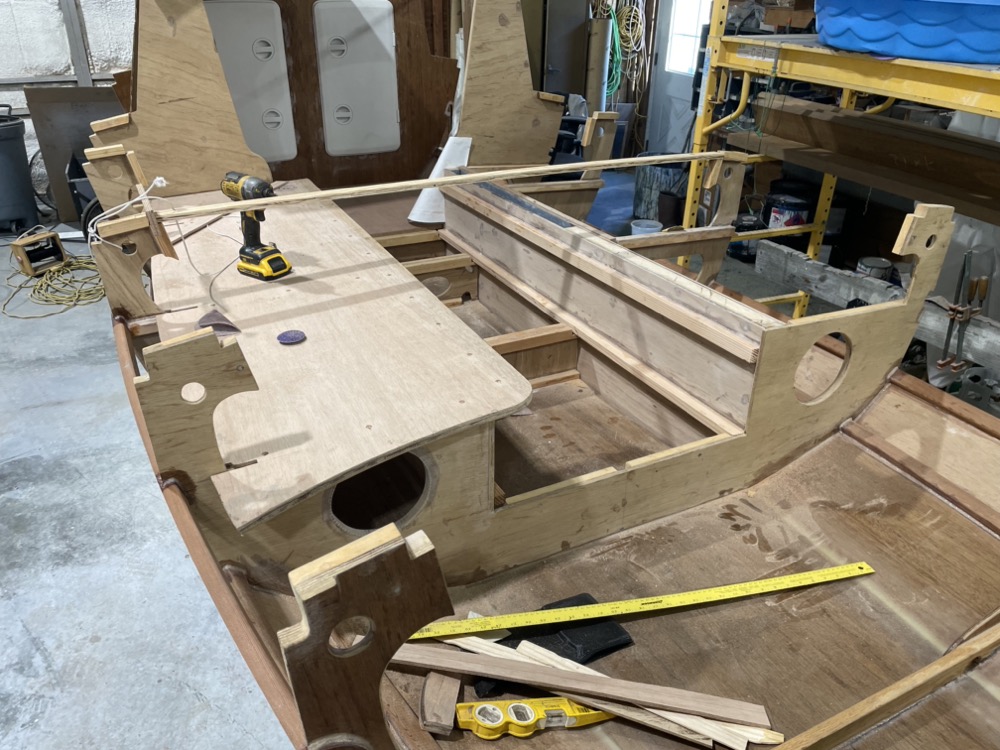
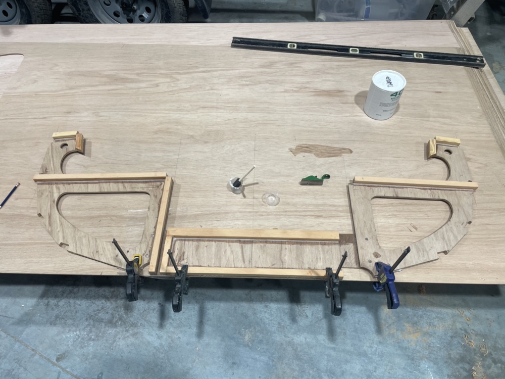
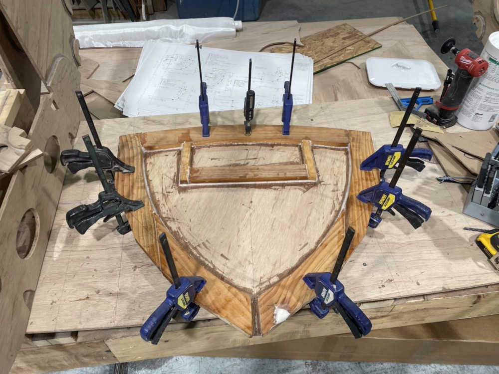
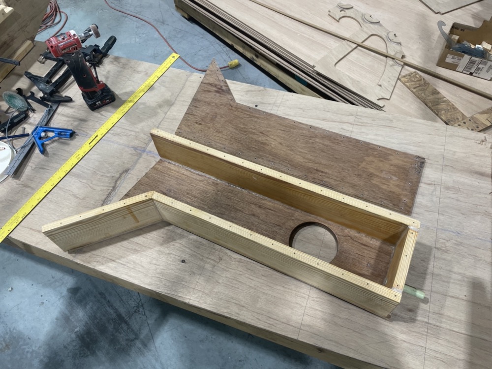
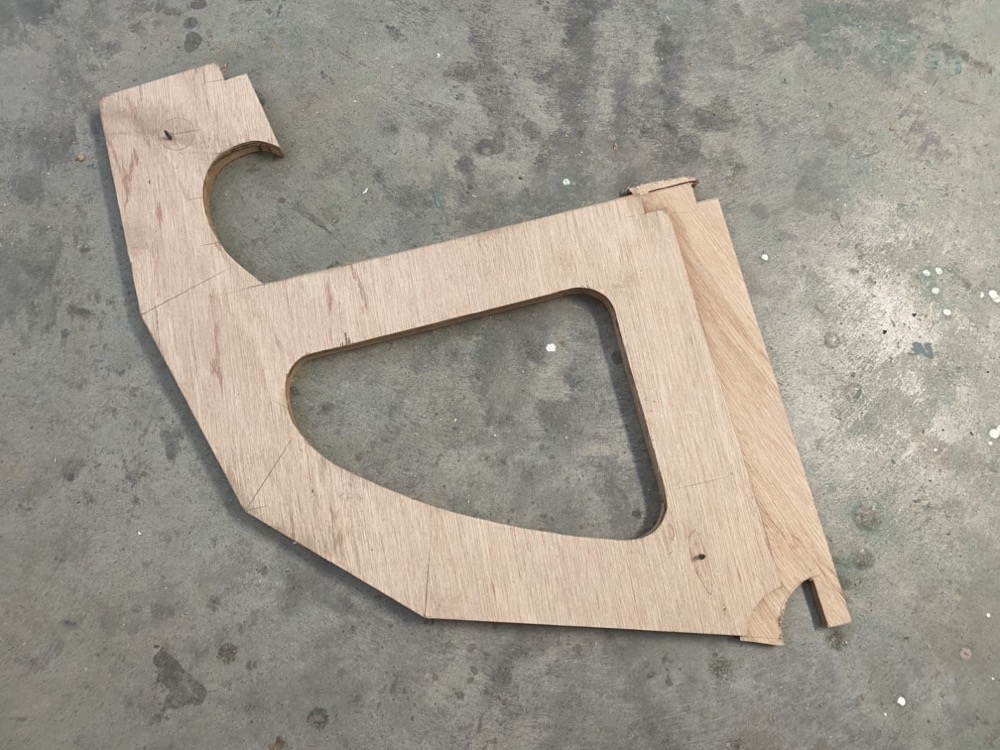
A few of the bulkheads are in two parts with asymmetrical sides so I found it easiest to mark a centerline and screw the parts to a sheet of ply with a few carefully measured reference points.
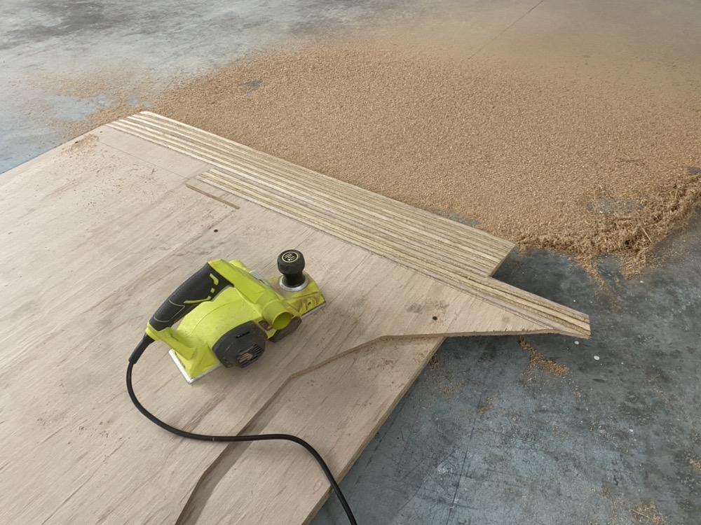
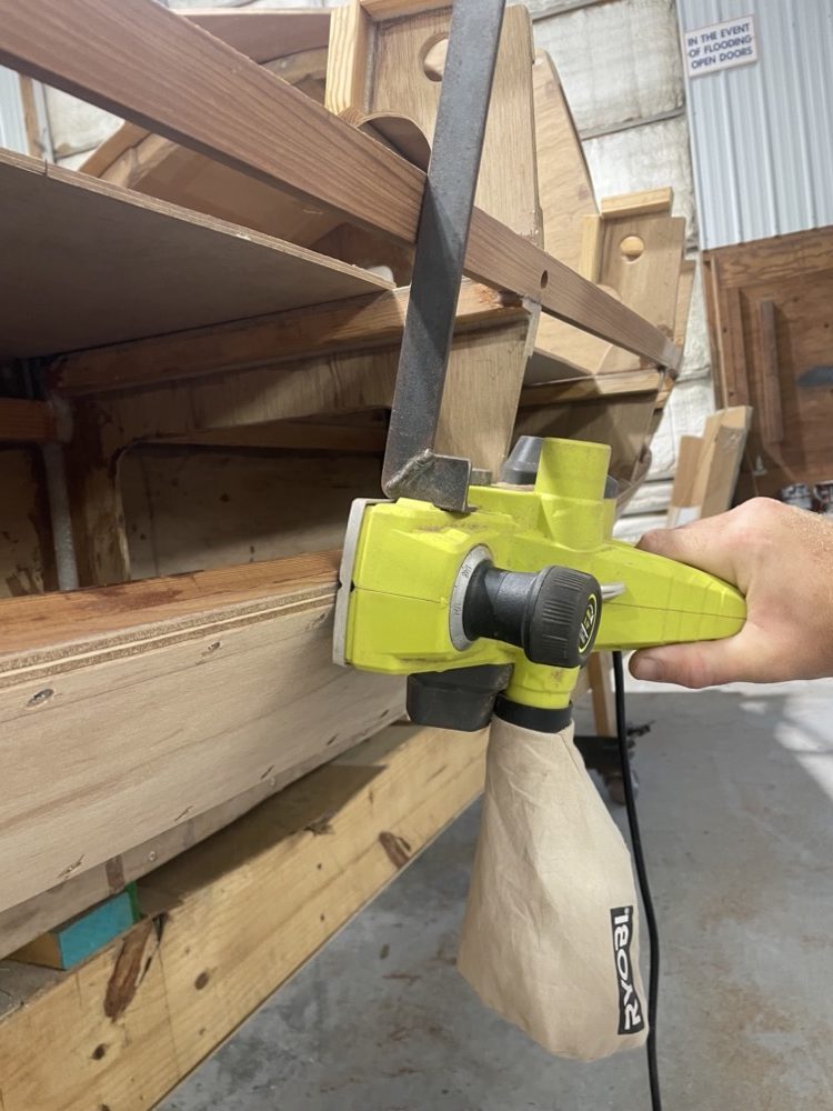
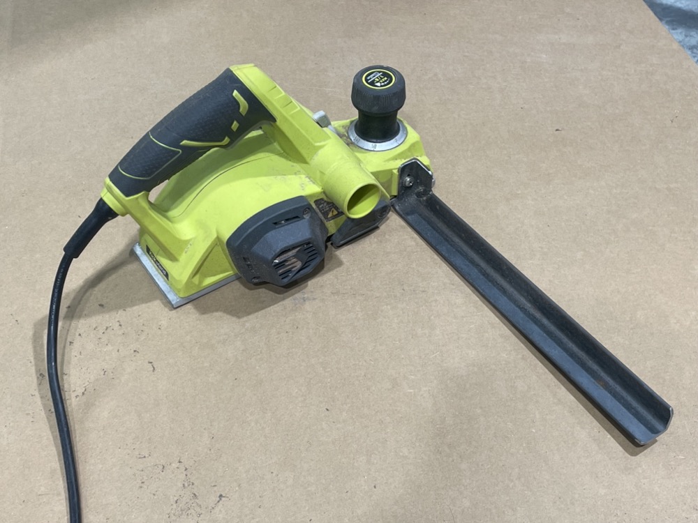
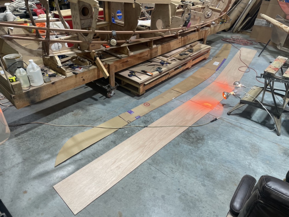
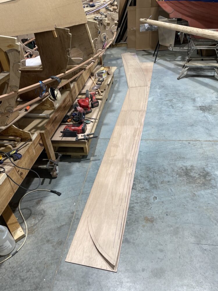
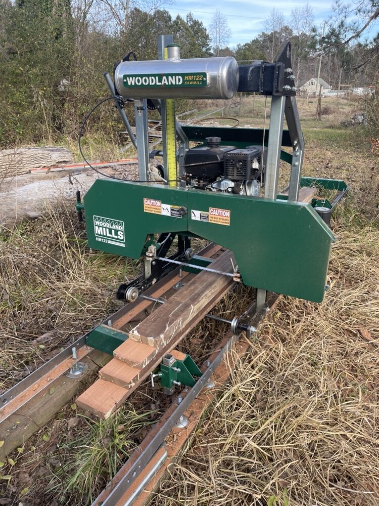
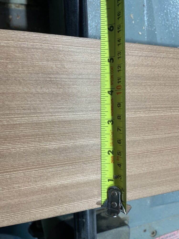
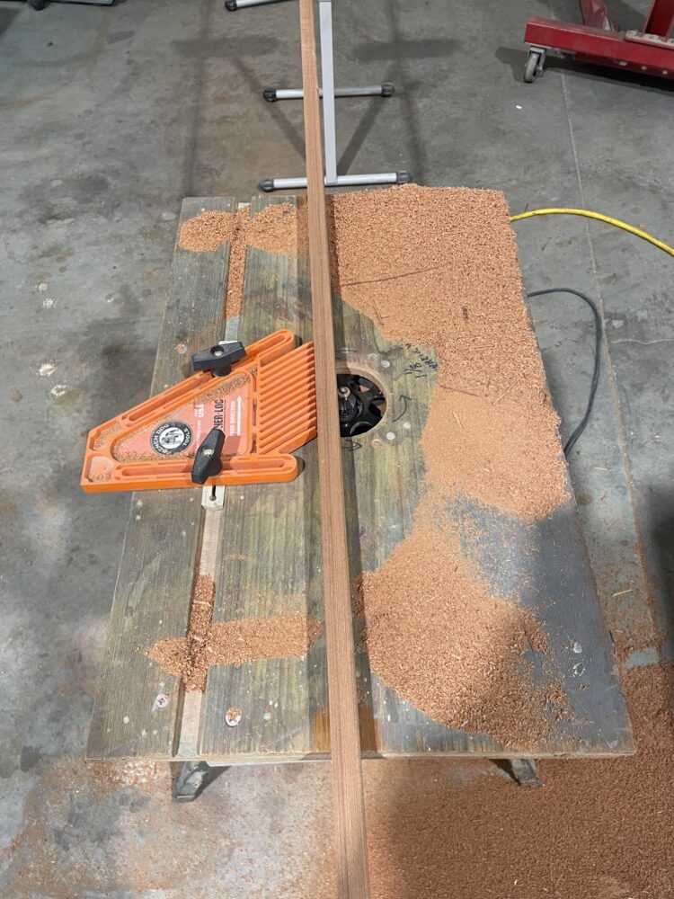
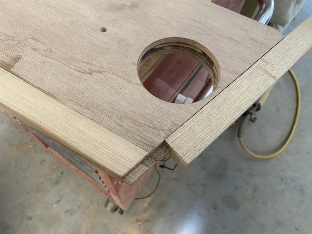
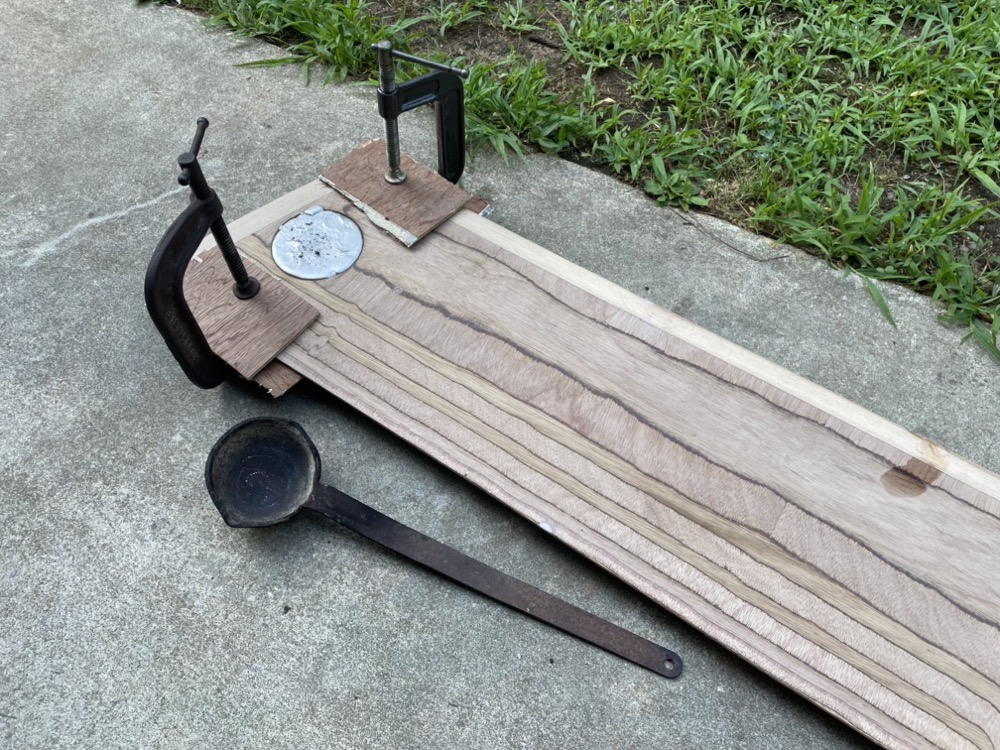
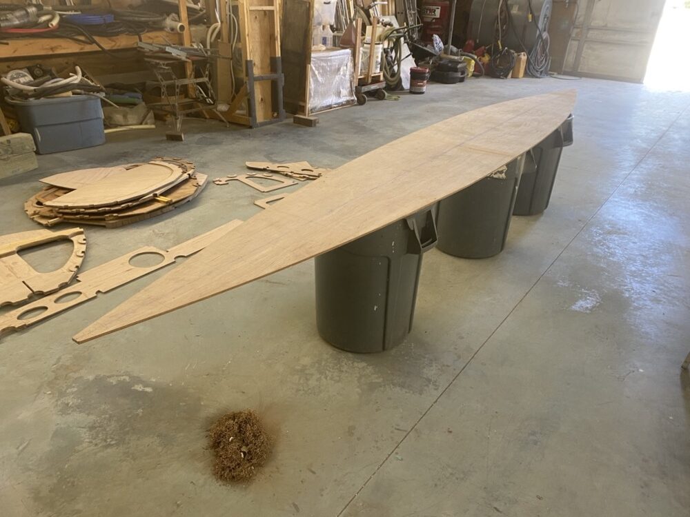
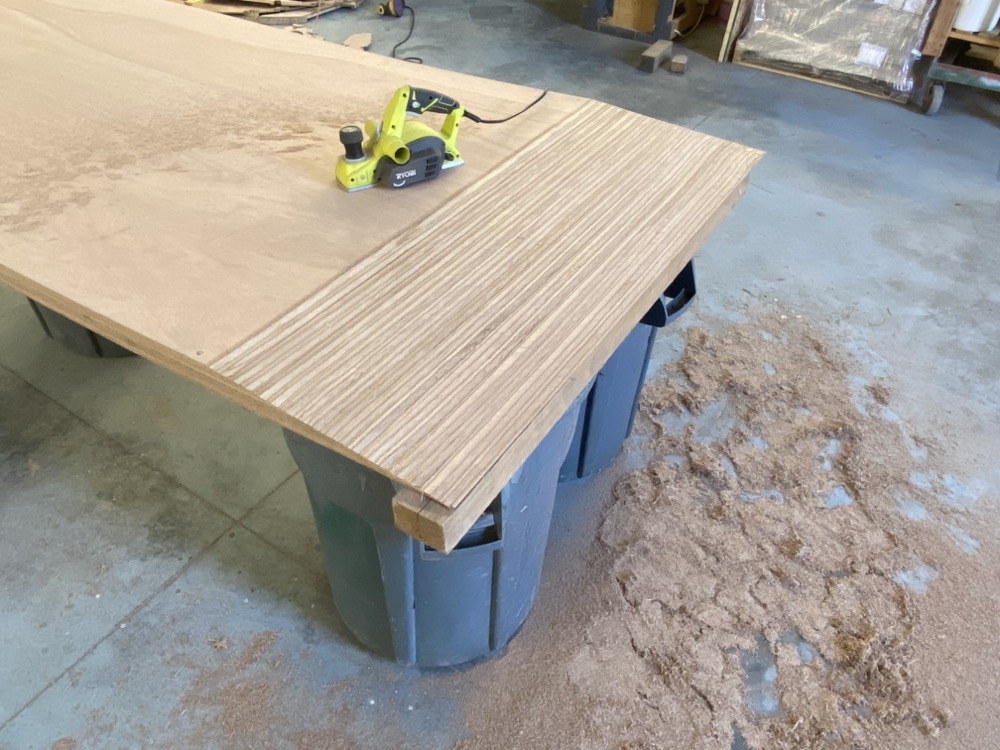
My wife and son are out of town for a week visiting family, so I’ve been staying at work till 9pm and making a lot of headway. I’ve finally got all the 3/8″ parts cut out so it was time to scarf the leftovers for the bottom panel. I’m doing an 8 to 1 scarf, so just draw a line 72mm back from the edge, screw the stack of wood together, and start planing until you end up with a slope from the line down to a feather edge. I gave this router the full Lou treatment and it is a real joy to use. https://youtu.be/_a1HCqK5i-A
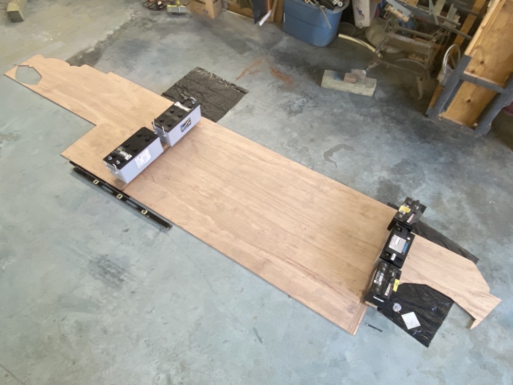
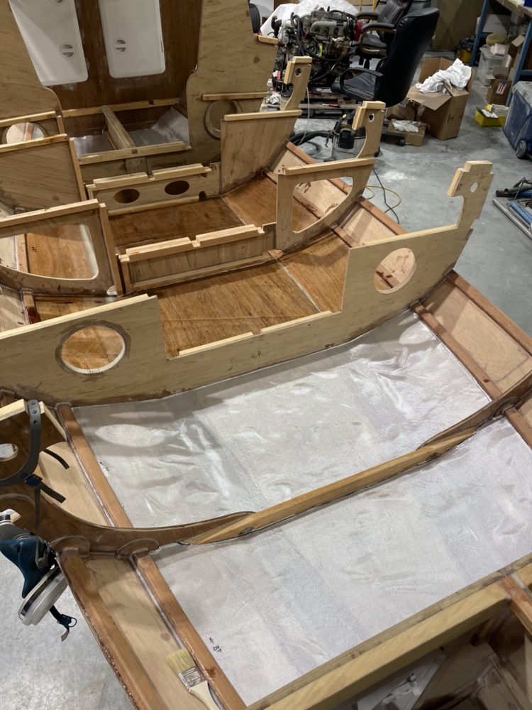
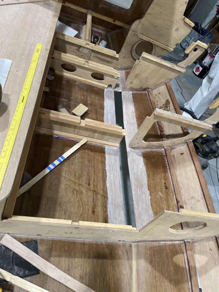
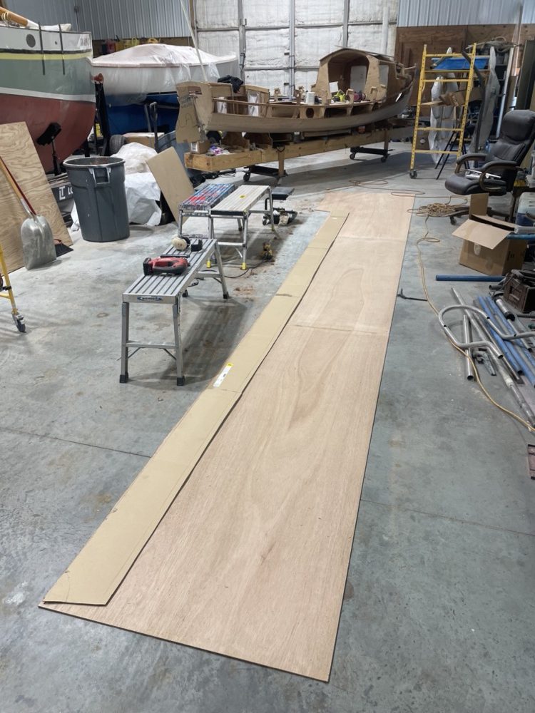
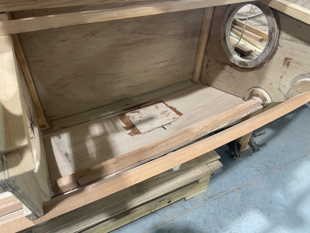
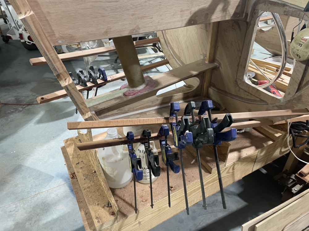
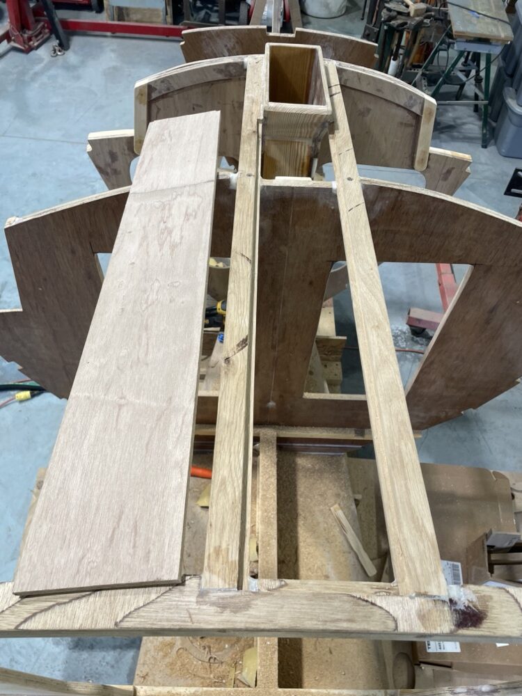
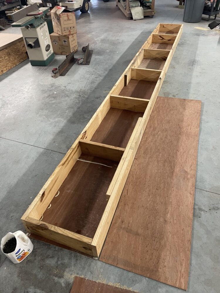
Next I epoxied the sheets together and used some old batteries and 2x4s to concentrate the weight right on the scarf. The bottom panel will run from between the cut out parts on the left, through the full sheet, and halfway into the section on the right. One side of the centerboard case will come out of the bottom along with two layers of rudder.
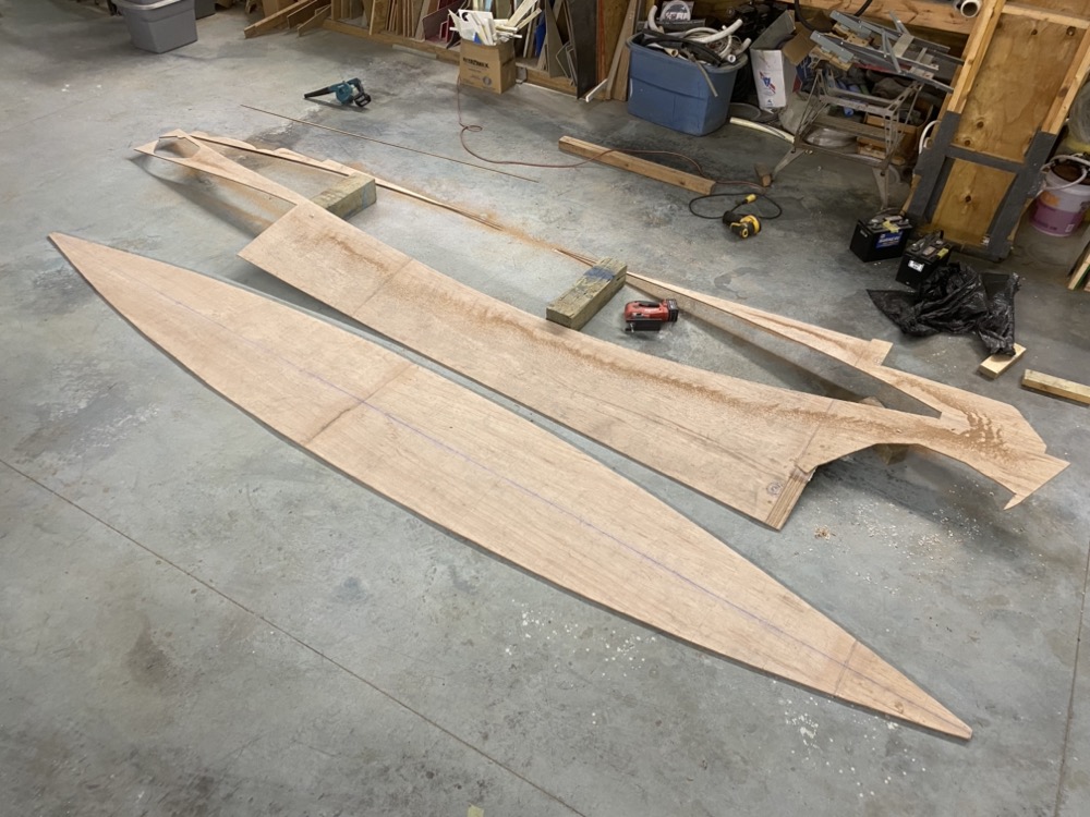
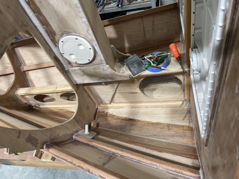
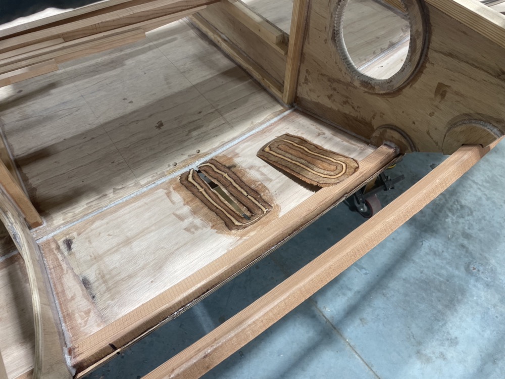
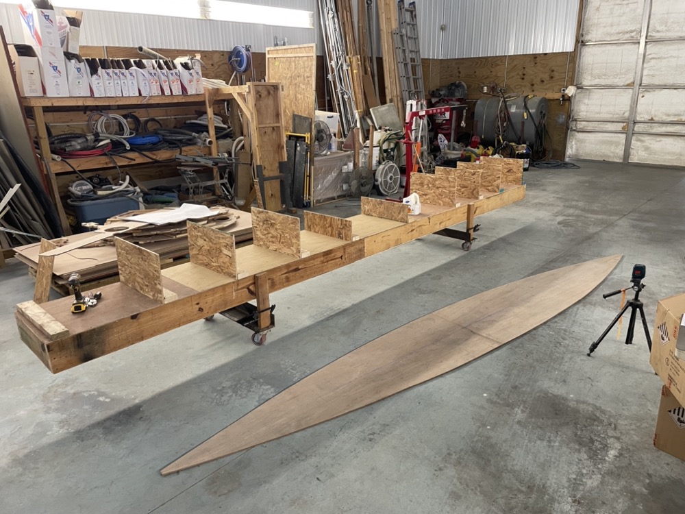
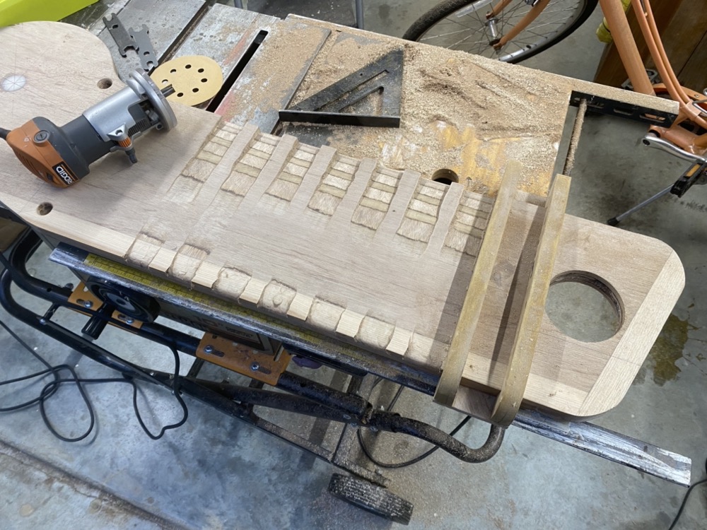
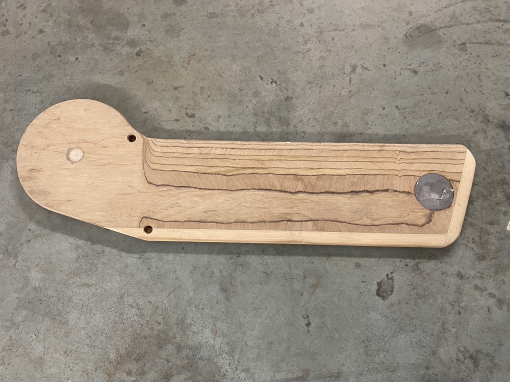
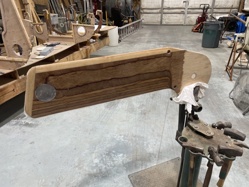
After the epoxy cured I struck a centerline and laid out the bulkhead locations and points for a batten to define the edge. The scarfs came out pretty good and a light sanding got them pretty flat. I’ll get the centerboard case and two rudder blanks out of the section that’s left.
Next I took the edge down to the line with a little plane.
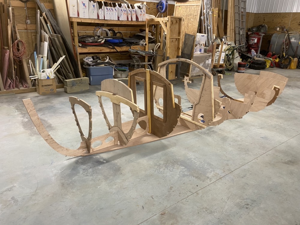
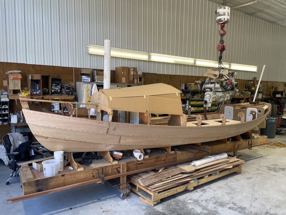
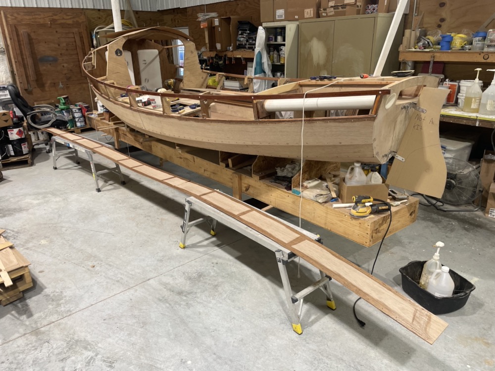
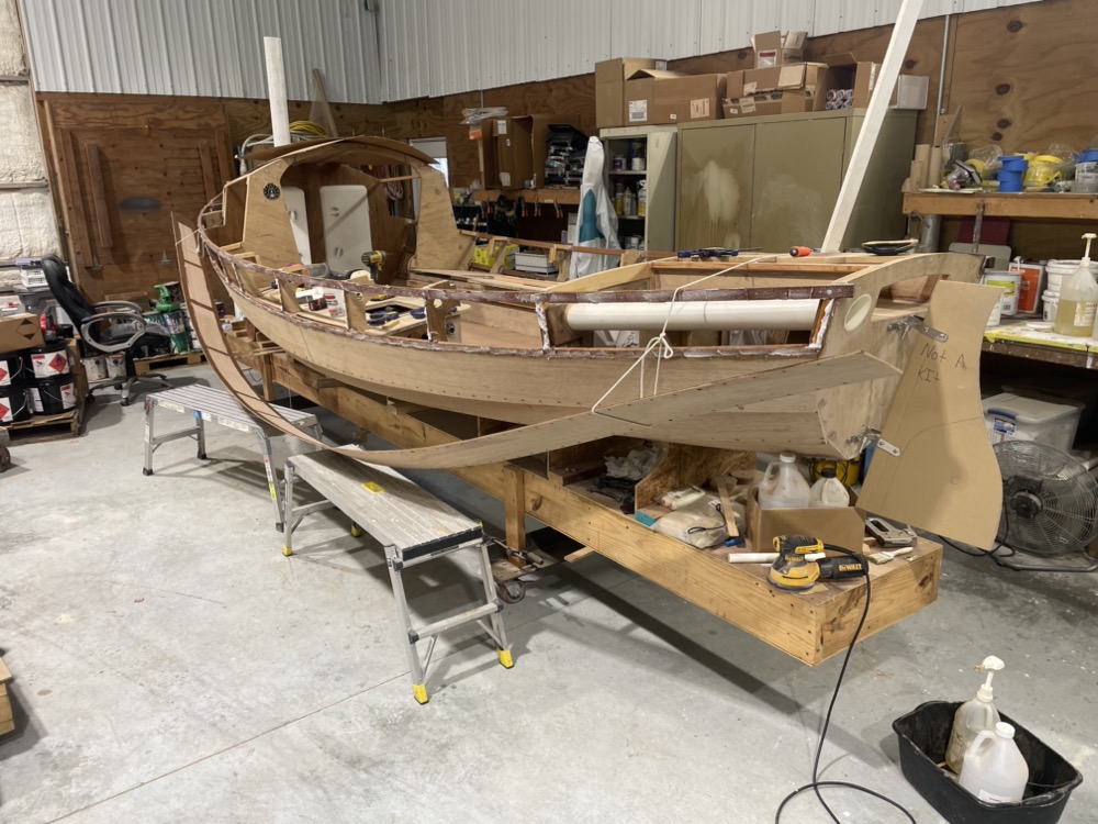
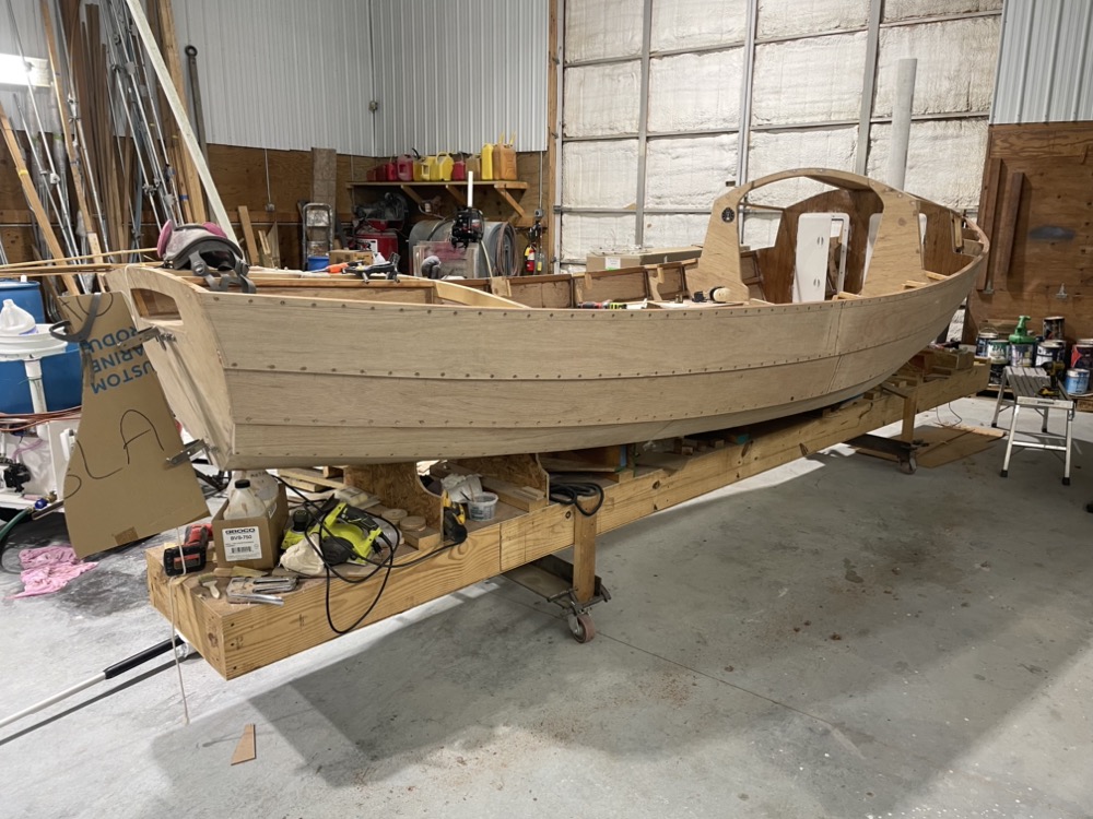
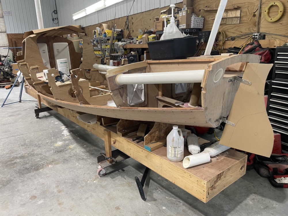
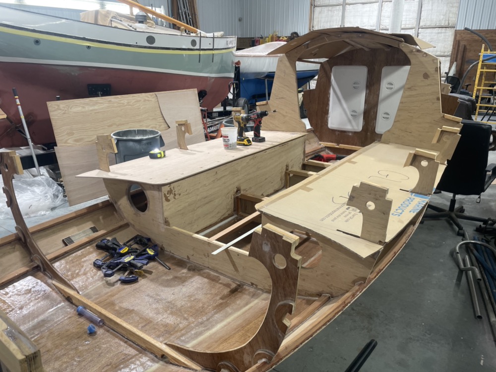
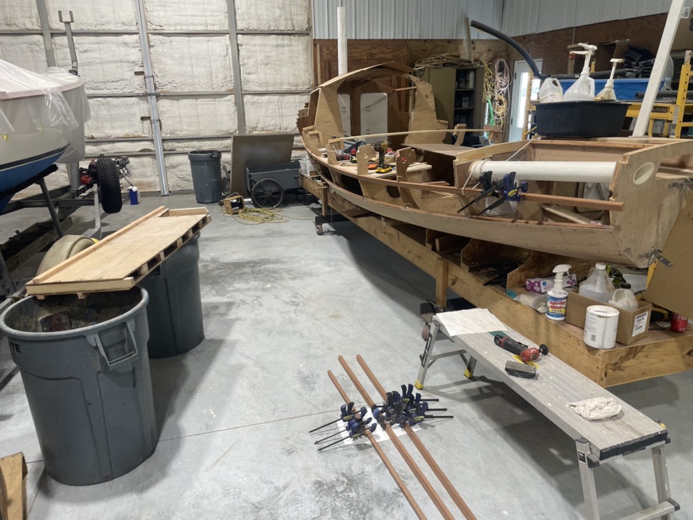
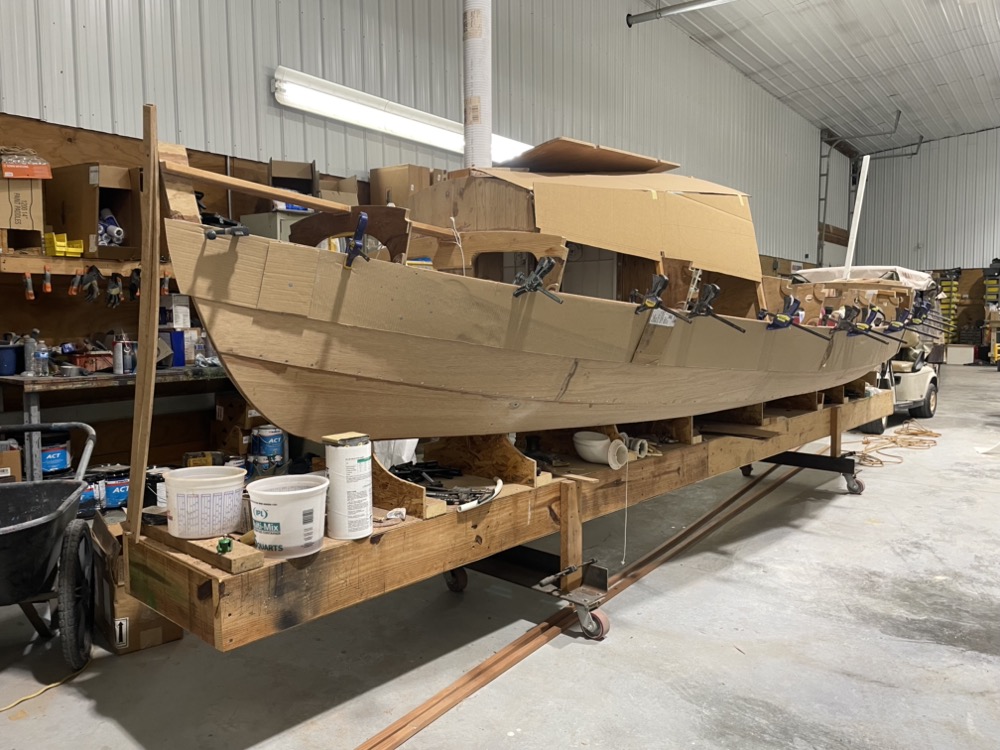
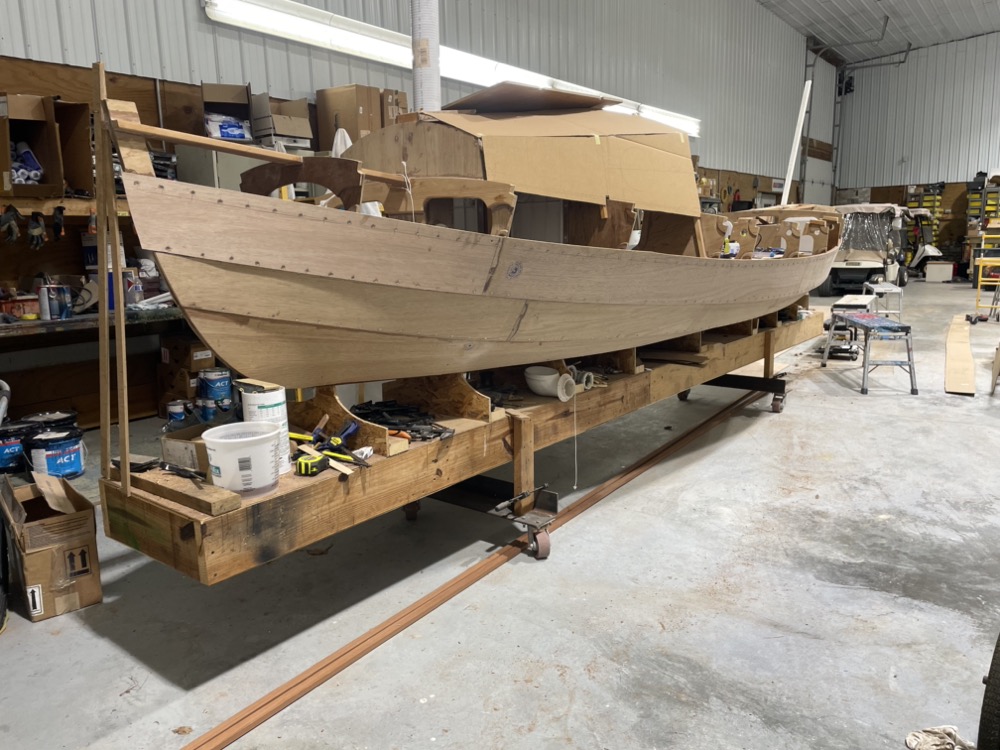
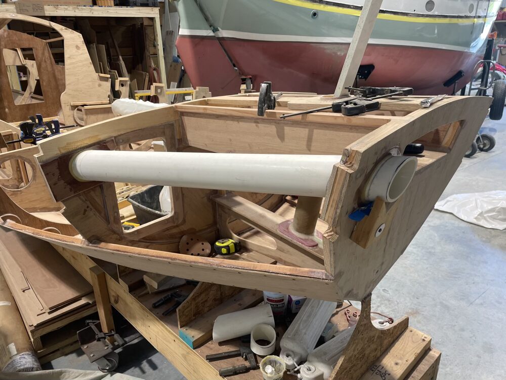
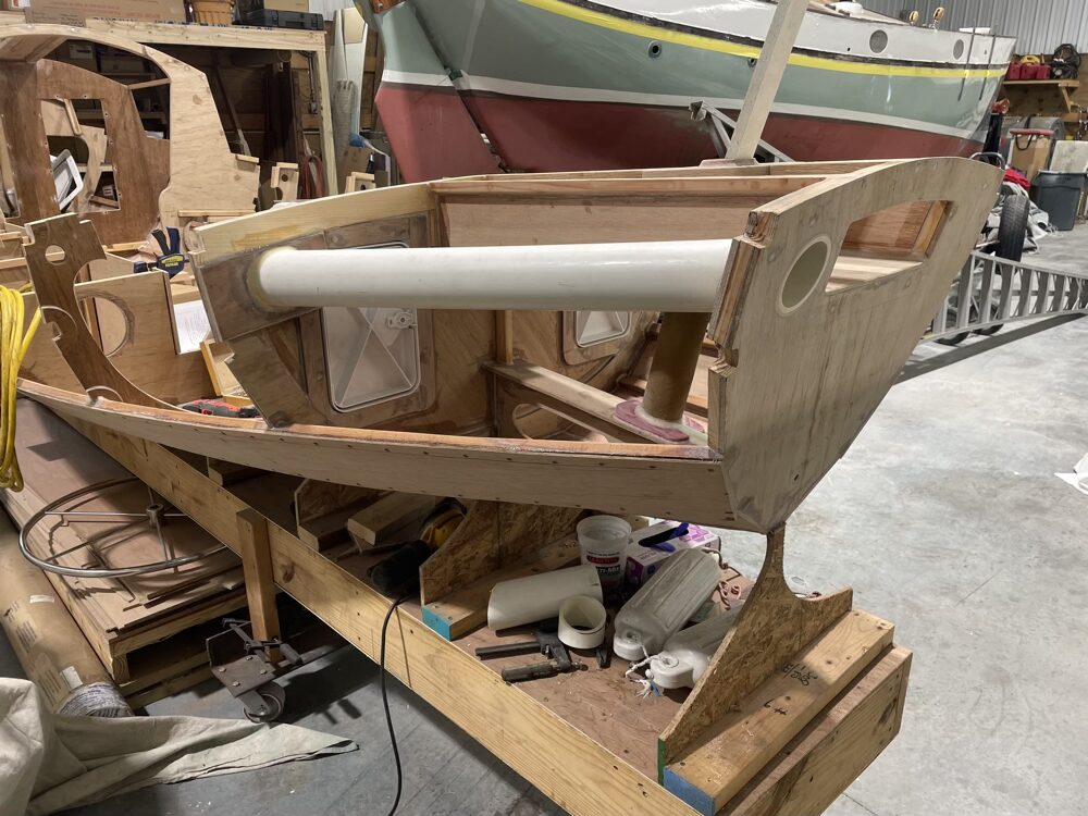
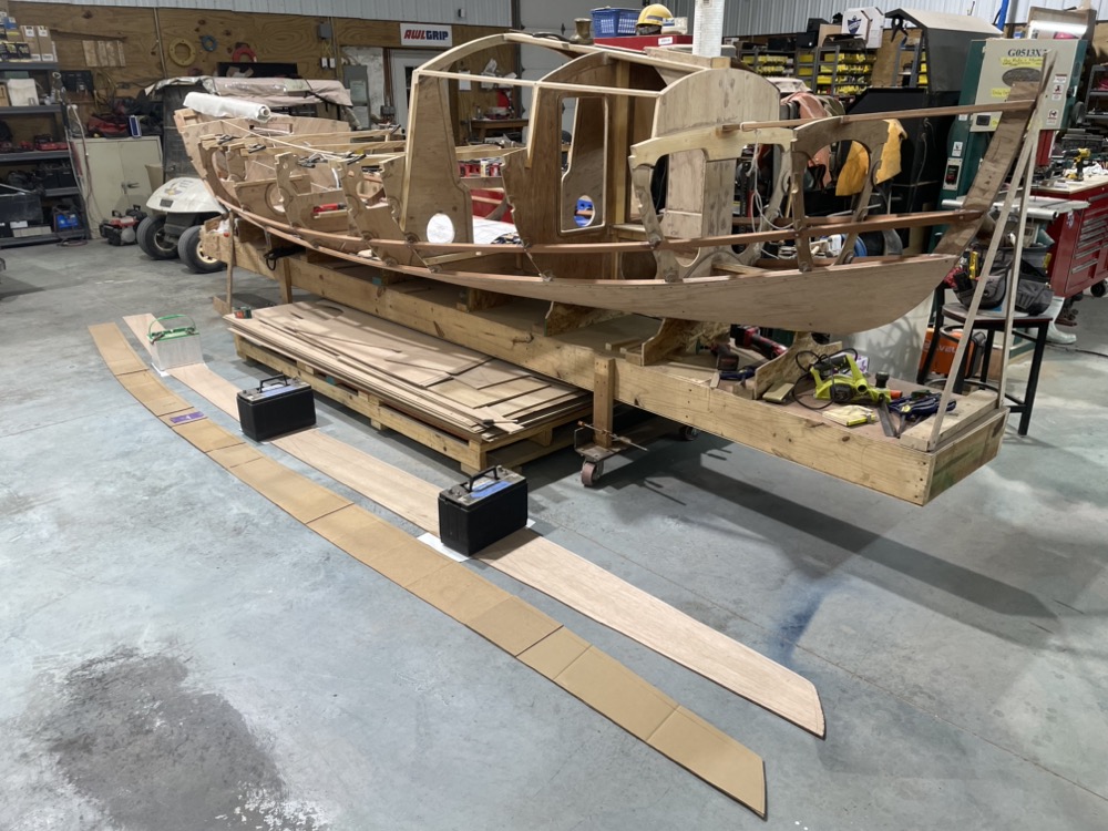
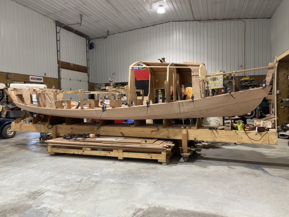
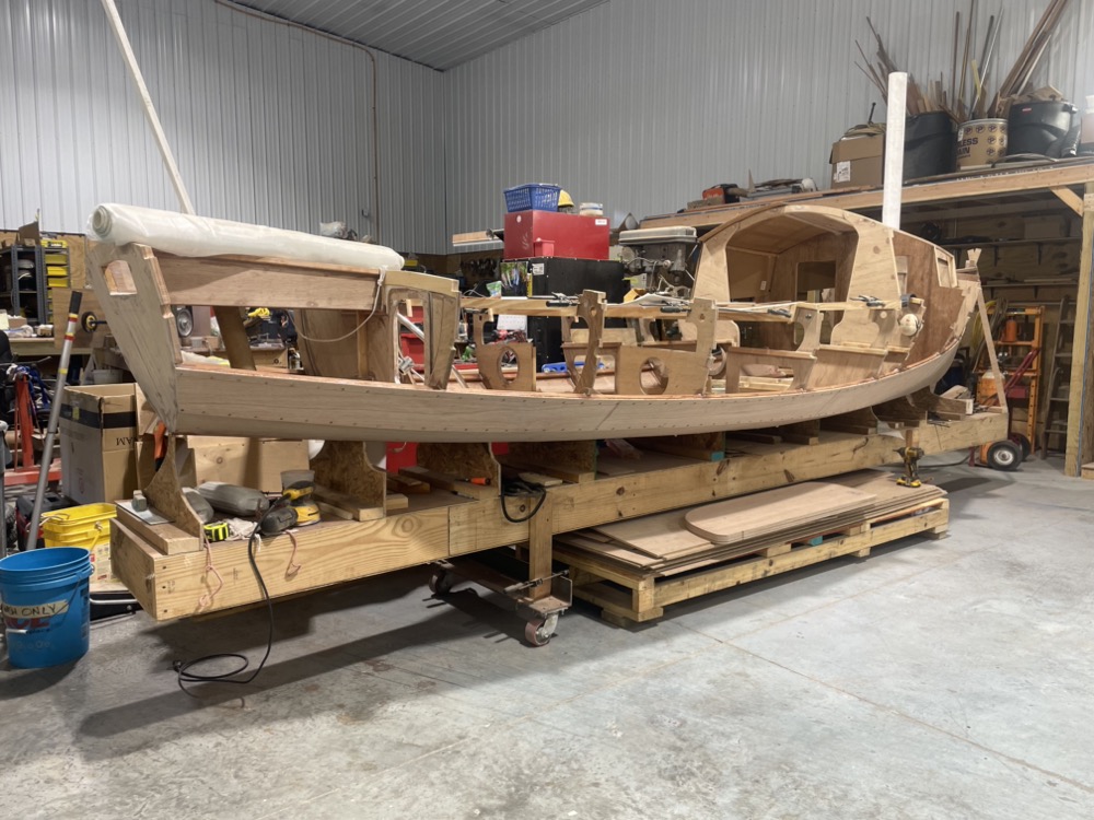
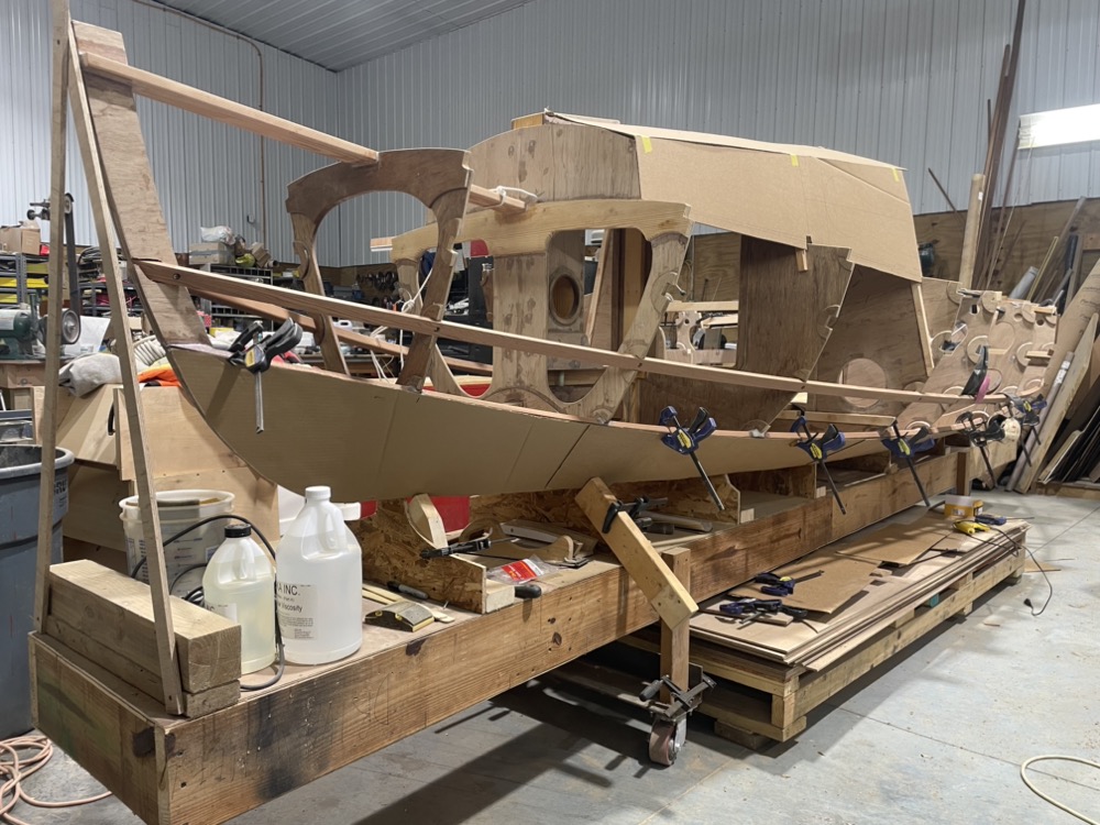
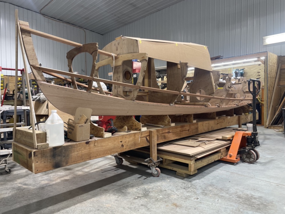
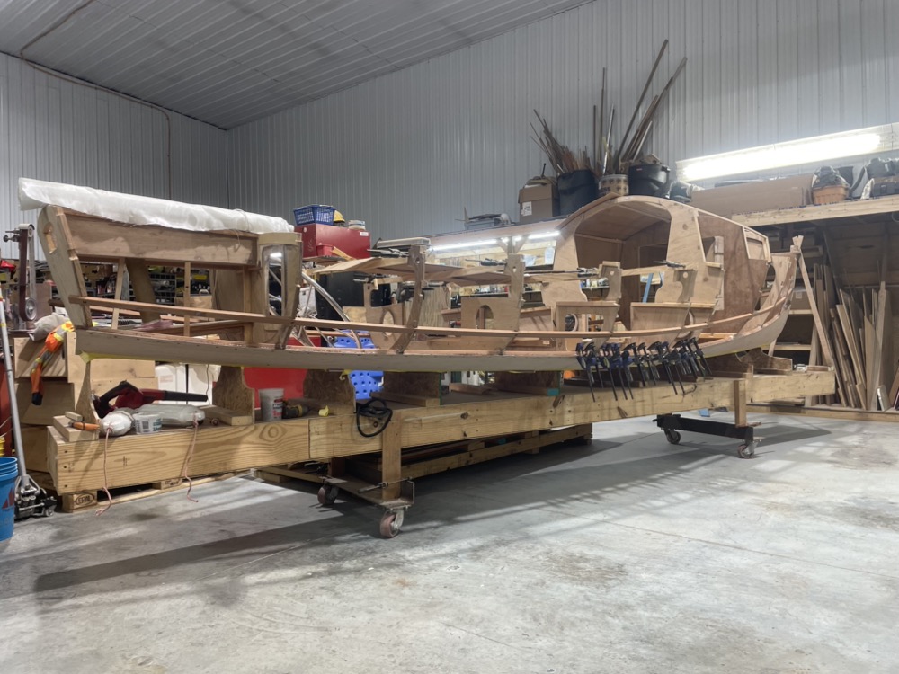
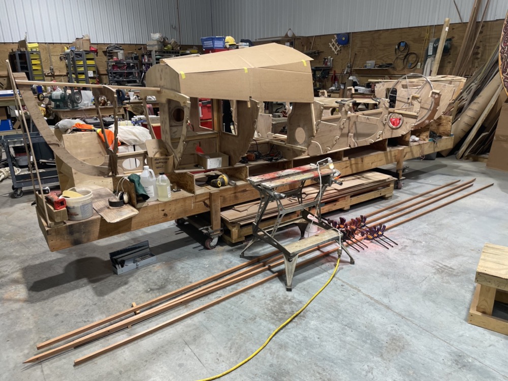
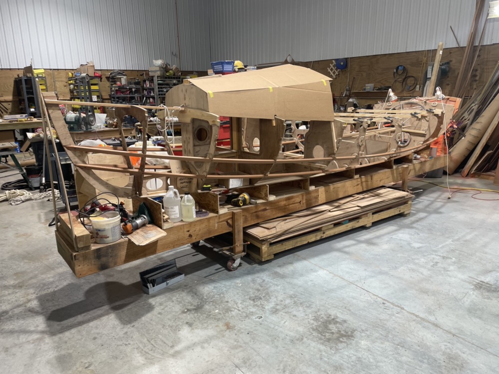
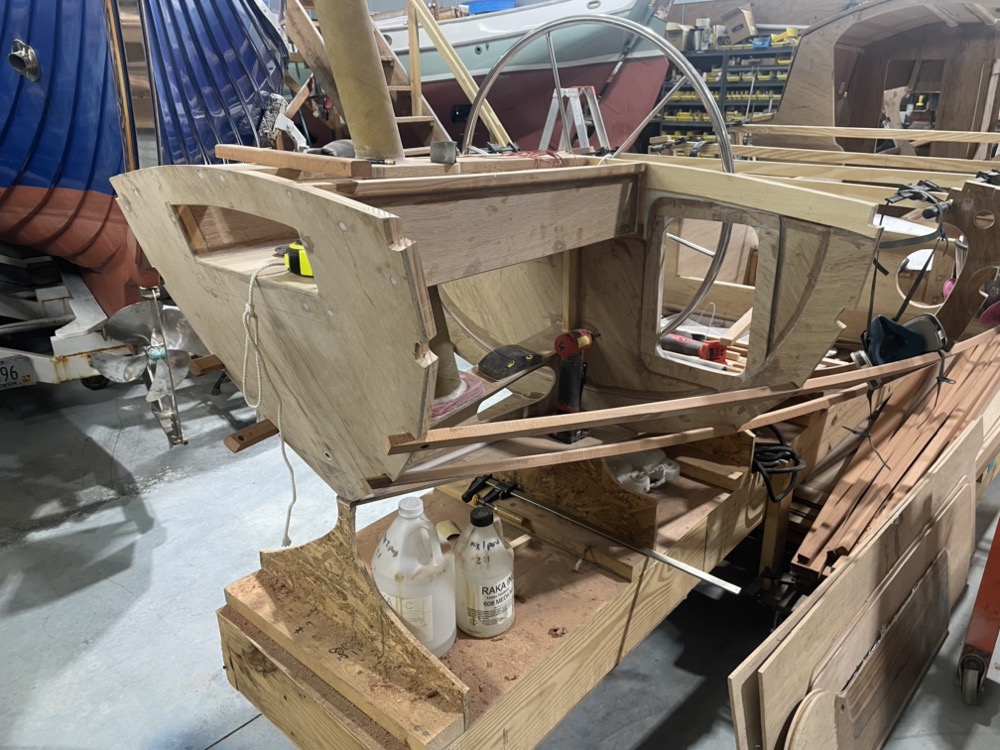
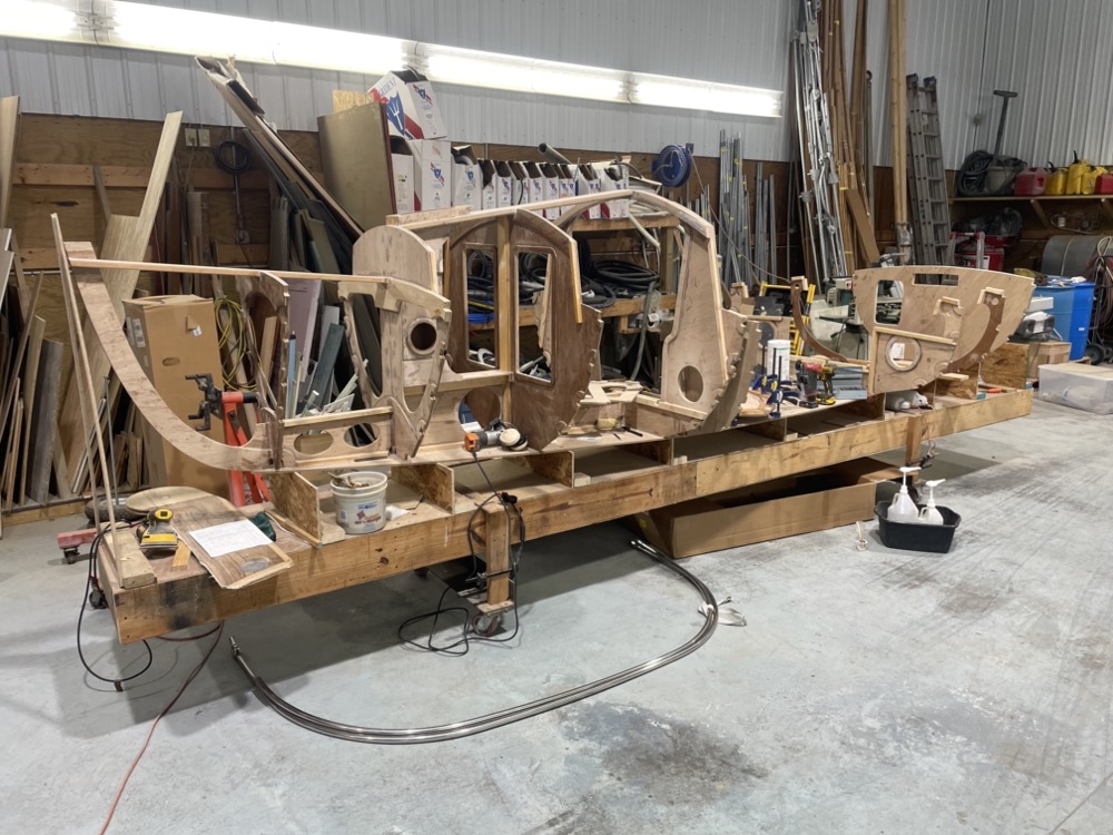
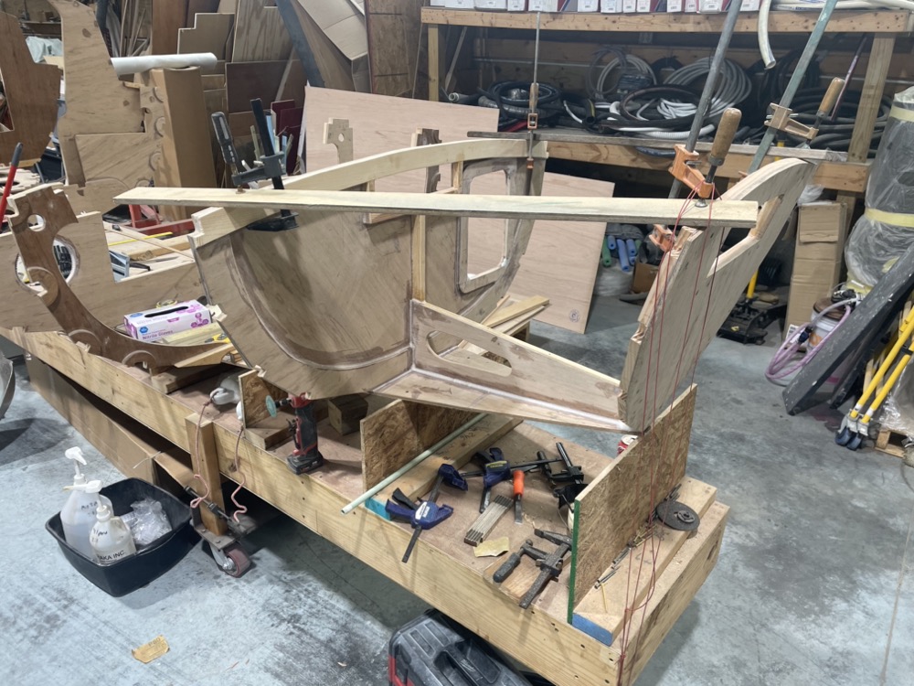
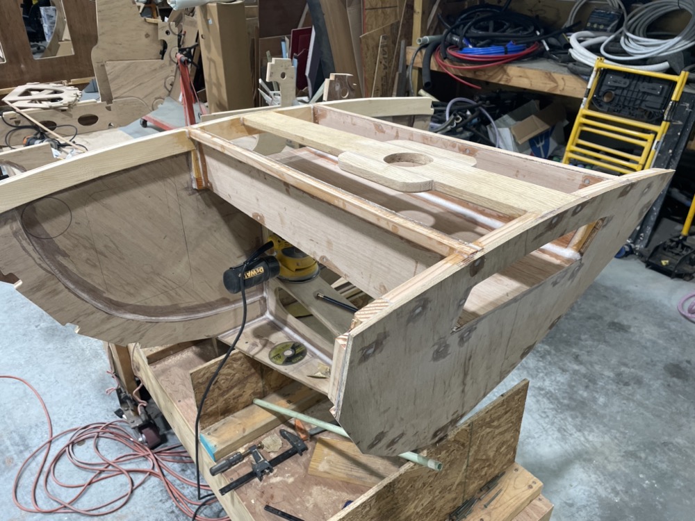
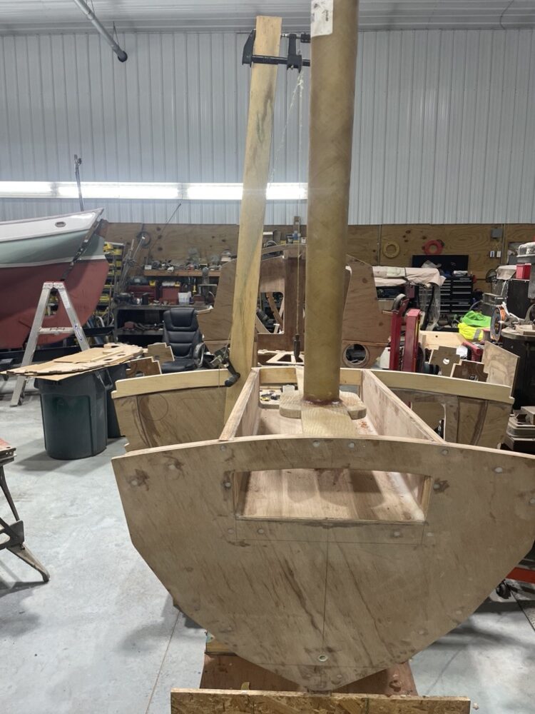
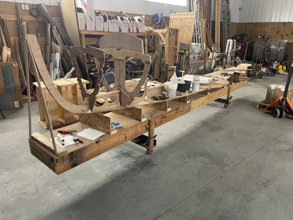
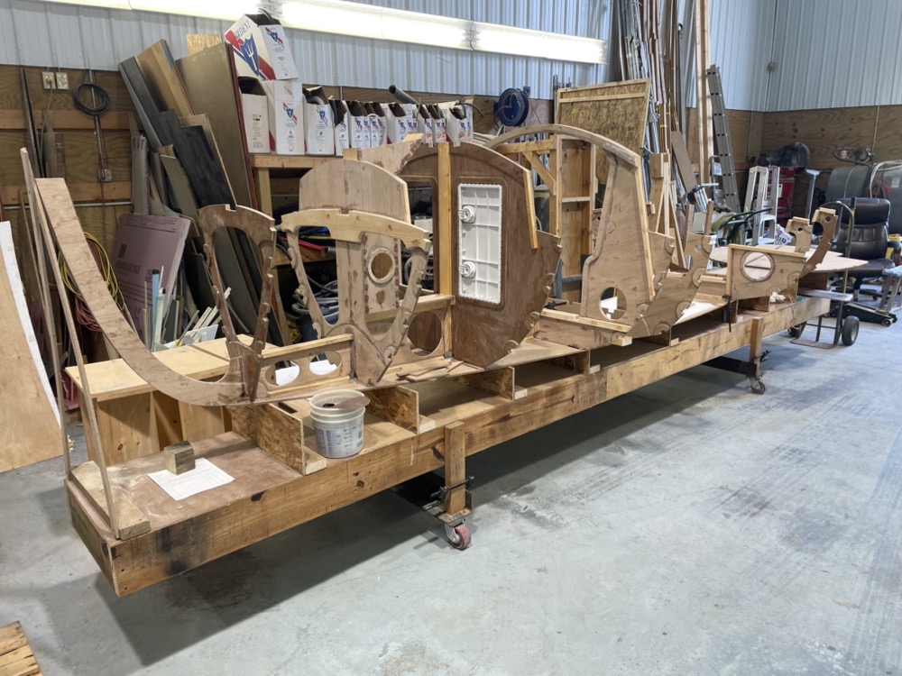
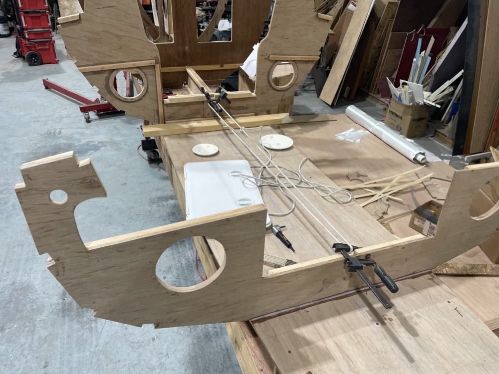
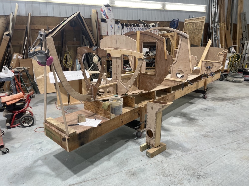
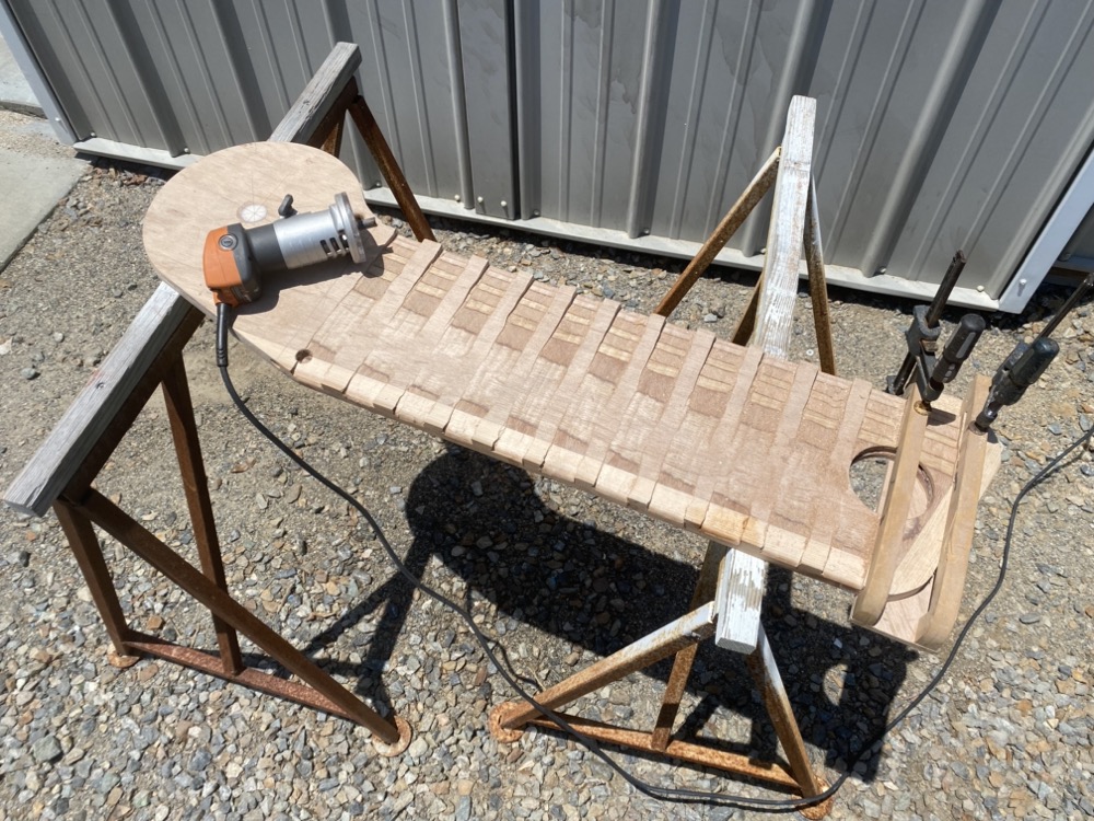
I set up all the frames on the bottom panel and finally got a look at the size which is both bigger and smaller than I imagined. It’s been a little difficult to get a sense of scale working with just a CAD model and metric dimensions. It’s bigger in the sense that while it’s only half a sheet of plywood longer than my First Mate, there’s way more storage space and I’m really going to enjoy the open center aisle for sleeping. It’s also smaller in that it feels like a totally doable project. When I was cutting out endless bulkheads and looking at my giant stack of plywood I really began wondering if I’d bitten off more than I could chew. I’m still quite a ways away from setting up a strong back since I need to get the bulkheads complete, but it was nice to stand there holding an imaginary tiller and thinking about going on adventures next year.
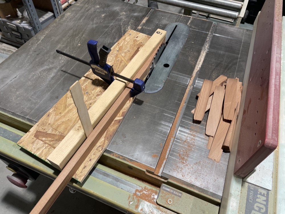
Try as I may there’s just no way to get all eight planks out of six sheets of plywood without doing a bunch of crazy angled scarfs. While I was in the scarfing mode I decided to get nine sheets ready for whenever I get to planking.
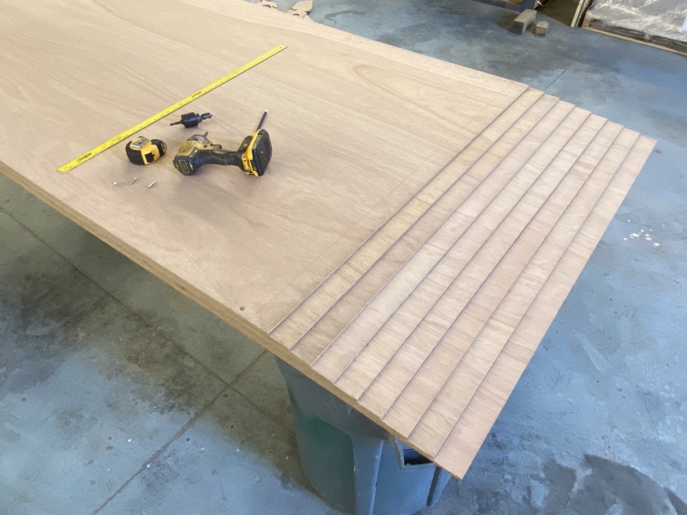
I set each sheet back 50mm from the edge and screwed them together in countersunk holes.
It took about 20 minutes to knock the corners off. I still need to do some hand planing I think up at the top, but it’s pretty good.